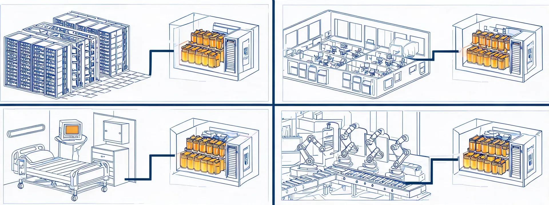
Critical power applications across facility types

Application-led selection

Eaton Ups planning by operating environment

The same apparent load can demand a different topology, autonomy, redundancy and maintenance pathway when availability targets, ambient conditions and upstream sources change.

Four environments, four review patterns

Data centers and network rooms

Continuous computing loads call for kW and power-factor confirmation, scalable redundancy, static and maintenance bypass planning, network monitoring, battery access and fault-domain boundaries. For a rack room, physical depth and outlet mapping can be as consequential as VA rating. For a larger plant, generator compatibility and input harmonic behavior enter the review.

Verify
Load steps, redundancy target, rack or floor footprint, Modbus TCP or network-card requirements.
Boundary
N+1 architecture cannot compensate for shared upstream or downstream single points of failure.

Healthcare and laboratories

Clinical and analytical equipment may combine sensitive electronics with pulsed or nonlinear loads. The project team must separate code-required emergency functions from equipment that merely benefits from conditioned power, then coordinate transfer behavior, isolation, alarms and maintenance access with the responsible electrical engineer.

Verify
Critical branch interface, leakage constraints, transfer sequence, service window and local requirements.
Boundary
A UPS does not replace a compliant emergency power system or clinical risk assessment.

Manufacturing and process control

PLCs, industrial networks and instrumentation often need ride-through, while drives, heaters and motors may be unsuitable for the same UPS output. Segregating control loads from high-inrush equipment can reduce oversizing. Dust, heat, vibration and enclosure conditions also influence installation and battery expectations.

Verify
Inrush, regenerative behavior, 50/60 Hz frequency, ambient temperature and shutdown sequence.
Boundary
Motor starting and variable frequency drive loads require waveform and overload review.

Commercial and distributed facilities

Security, access control, communications and building-management loads are frequently spread across several electrical rooms. A distributed design can isolate local faults and simplify phased deployment; a centralized design can concentrate maintenance and monitoring. Cable routes, tenant access and service staffing determine which benefit matters more.

Verify
Panel locations, branch circuits, autonomy by function, alarm integration and replacement access.
Boundary
Distributed batteries increase inspection points; centralized systems increase consequence at a common node.

Selection checklist

Bring these facts to an application review. They establish the reproducible basis for a runtime calculation and configuration discussion.

  • Nominal input and output voltage, phase and frequency
  • Present kW/kVA load plus measured or expected growth
  • Power factor, nonlinear content and largest load step
  • Required runtime at stated load and end-of-life assumptions
  • Redundancy, bypass and upstream protective-device arrangement
  • Ambient temperature, altitude, access and ventilation
  • Network management, dry contacts and protocol requirements
  • Destination market and product-series compliance evidence

Centralized or distributed?

Centralized architecture

Consolidated monitoring and maintenance can be simpler, and larger equipment may use space efficiently. The trade-off is a broader fault domain and potentially longer distribution paths.

Distributed architecture

Local autonomy can isolate faults and align capacity with phased spaces. The trade-off is more batteries, inspection points and network nodes to administer.

Map the application before comparing models

Send a one-line diagram and load schedule; we will return the missing-input list and selection checkpoints.

Submission is handled according to our Privacy Policy.